The Basics of Electricity
This section includes basic info on; Resistance, Voltage, Coils, Transformers, Rectifiers and Power Supplies, Voltage Doublers and more to come.
What Is Resistance
Being familiar with Voltage and Resistance is the key to understanding electronic circuitry. Resistance is a measure of how difficult it is for current to flow through something. Some materials such as glass, ceramics, wood and most plastics do not easily carry a current and so are considered to be ‘insulators’. That is why you will see power lines hung from their pylons by a series of ceramic discs. Current flows easily through metals, especially along the surface of the metal, so cables are made from metal wires surrounded by a layer of plastic insulation. The higher grade cables have wire cores made up of many small-diameter strands as this increases the surface area of the metal for any given cross-sectional area of the metal core (it also makes the cable more flexible, and generally, more expensive).
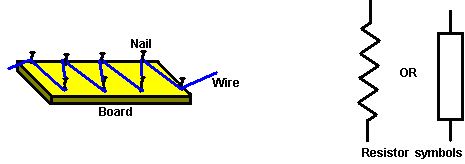
There is a very important, third group of materials, silicon and germanium in particular, which fall between conductors and insulators. Not surprisingly, these are called ‘semi-conductors’ and the amount of current they can carry depends on the electrical conditions in which they are placed. Much, much more about this later on. While a metal wire carries current very well, it is not perfect at the job and so has some ‘resistance’ to current flowing through it. The thicker the wire, the lower the resistance. The shorter the wire, the lower the resistance. The first researchers used this characteristic to control the way circuits operated. Sometimes, as higher resistances were needed, the researcher used to need long lengths of wire which would get tangled up. To control the wire, a board with nails along each side was used and the wire wound backwards and forwards across the board. Image Credit and Source Coils
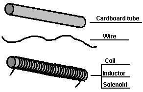
If you take a cardboard tube, any size, any length, and wind a length of wire around it, you create a very interesting device. It goes by the name of a ‘coil’ or an ‘inductor’ or a ‘solenoid’.
This is a very interesting device with many uses. It forms the heart of a radio receiver, it used to be the main component of telephone exchanges, and most electric motors use several of them. The reason for this is if a current is passed through the wire, the coil acts in exactly the same way as a bar magnet: 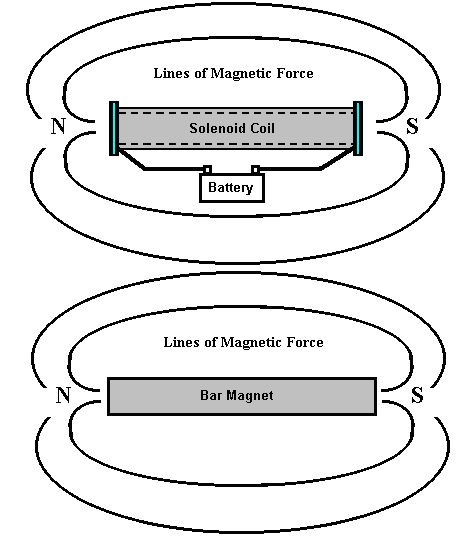
The main difference being that when the current is interrupted, the coil stops acting like a magnet, and that can be very useful indeed. If an iron rod is placed inside the coil and the current switched on, the rod gets pushed to one side. Many doorbells use this mechanism to produce a two-note chime. A ‘relay’ uses this method to close an electrical switch and many circuits use this to switch heavy loads (a thyristor can also be used for this and it has no moving parts).
A coil of wire has one of the most peculiar features of almost any electronic component. When the current through it is altered in any way, the coil opposes the change. Image Credit and Source Rectification and Power Supplies
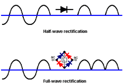
We now have the question of how do we turn an alternating voltage into a constant ‘direct’ voltage. The crystal radio set operates by chopping off half of the alternating radio signal. If we were to do this to the output from a mains transformer with an output of say, 12 Volts AC, the result is not very satisfactory:
Here, we have the situation shown in the upper diagram. The output consists of isolated pulses at 50 per second. You will notice that there is no output power for half of the time. The negative part of the waveform is blocked by the high resistance of the diode while the positive part of the waveform is allowed through by the low resistance of the ‘forward-biased’ diode. It should be remembered that the diode drops 0.7 Volts when conducting so the output of the half-wave rectified transformer will be 0.7 Volts lower than the transformer’s actual output voltage. If four diodes are used instead of one, they can be arranged as shown in the lower diagram. This arrangement of diodes is called a ‘bridge’. Here the positive part of the waveform flows through the upper blue diode, the load ‘L’ and on through the lower blue diode. The negative part flows through the left hand red diode, the load and then the right hand red diode. This gives a much better output waveform with twice the power available. The output voltage will be 1.4 Volts less than the transformer output voltage as there are two silicon diodes in the supply chain. The output from even the full-wave rectifier is still unsatisfactory as there is a voltage drop to zero volts 100 times per second. Only a few devices operate well with a power supply like that, an incandescent bulb as used in a car can use this output, but then, it could use the original AC supply without any rectification. We need to improve the output by using a reservoir device to supply current during those moments when the voltage drops to zero. The device we need is a Capacitor which used to be called a ‘condenser’. The circuit of a mains unit using a capacitor is shown here: 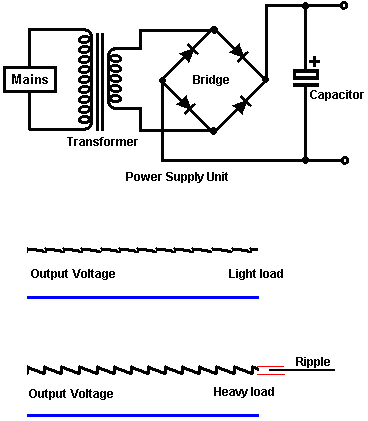
This produces a much better result as the capacitor stores some of the peak energy and gives it out when the voltage drops. If the load on the unit is light with not very much current taken from it, the output voltage is quite good. However, if the current drain is increased, the output voltage gets dragged down 100 times per second. This voltage variation is called ‘ripple’ and if the unit is supplying an audio system or a radio, the ripple may well be heard as an annoying hum. The larger the capacitor for any given current draw, the smaller the ripple.
To improve the situation, it is normal to insert an electronic control circuit to oppose the ripple: 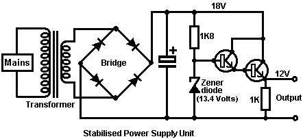
This circuit uses one new component, a new variety of diode called a ‘Zener’ diode. This device has an almost constant voltage drop across it when its current-blocking direction breaks down. The diode is designed to operate in this state to provide a reference voltage. The circuit merely uses a tiny current from the top of the zener diode to drive the Darlington pair emitter-follower transistors used to provide the output current.
With this circuit, when the output current is increased, the resistance of the transistor pair automatically reduces to provide more current without varying the output voltage. The 1K resistor is included to give the transistors a completed circuit if no external equipment is connected across the output terminals. The zener diode is chosen to give 1.4 Volts more than the required output voltage as the two transistors drop 1.4 Volts when conducting. You should note that the output transistor is dropping 6 Volts at the full supply current. Watts = Volts x Amps so the power dissipated by the transistor may be quite high. It may well be necessary to mount the transistor on an aluminium plate called a ‘heat sink’ to keep it from overheating. Some power transistors, such as the 2N3055, do not have the case isolated from the active parts of the transistor. It is good practice to use a mica gasket between the transistor and the heat-sink as it conducts then heat without making an electrical connection to the metal heat-sink. A capacitor, being an electrical reservoir, can be used as part of a timer circuit. If the current flow into it is restricted by passing it through a resistor. The length of time between starting the flow on an empty capacitor, and the voltage across the capacitor reaching some chosen level, will be constant for a high-quality capacitor. 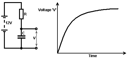
As the voltage increase tails off, it becomes more difficult to measure the difference accurately, so if the capacitor is to be used for generating a time interval, it is normal to use the early part of the graph area where the line is fairly straight and rising fast.
|
What is Voltage
Voltage is the key to understanding electronics. Without voltage, nothing happens in electronics. What is it? Nobody knows. We know how to generate it. We know what it does. We know how to measure it, but nobody knows what it actually is.
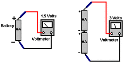
It is also called “Electro Motive Force” or “EMF” which is no help whatsoever in knowing what it is. That, is roughly equivalent to saying “the thing that pushes is the thing that pushes” - very true but absolutely no help whatsoever. OK, having admitted that we really don't know what it is, we can start to say the things we do know about it: A new battery has a voltage between its terminals. This voltage is said to cause a current to flow through any complete electrical circuit placed across it. The current flowing through the circuit can cause various things to happen such as creating light, creating sound, creating heat, creating magnetism, creating movement, creating sparks, etc., etc. By using the current caused by a voltage, a device called a ‘Voltmeter’ can indicate how big the voltage is. The bigger the voltage, the bigger the current and the bigger the display on the voltmeter. The voltmeter can have a numerical display where you read the voltage directly from the display, or it can be an ‘analogue’ voltmeter where the voltage is shown by the position of a needle on a scale. The size of the voltage is stated in ‘Volts’ which is a unit of measurement named after the man Volta who introduced voltage to the world (it was always there, we just did not know about it). Voltages add up if they are connected the same way round, i.e. with the + terminals all facing the same way: Image Credit and Source Transformers
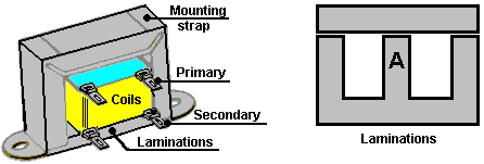
Transformers are used to alter the voltage of any alternating current power source. If the alteration increases the output voltage, then the transformer is called a ‘step-up’ transformer. If the output voltage is lower than the input voltage then it is called a ‘step-down’ transformer. If the voltages are the same, it is called an ‘isolation’ transformer. A common construction is shown next to this paragraph.
The Coil bobbin sits on the section of the laminations marked ‘A’ above. The coil is wound on its bobbin former, first one winding and then the second winding. The bobbin is then placed on the central part of the ‘E’ shaped laminations and then completely surrounded by the laminations when the crossbar is placed on the top. The mounting strap is used to hold the two sets of laminations together and provide mounting lugs for attaching the transformer to a chassis. There are typically, twenty laminations in each set and every lamination is insulated from the adjoining laminations. If you want to change the voltage of a battery supply, it is possible to build an electronic circuit to generate an alternating voltage and then use a transformer to change that alternating voltage to whatever voltage you want. The most common form of this, is for generating mains voltage from a 12 Volt car battery, so that mains equipment can be run in remote locations, such as boats, caravans, etc. These circuits are called ‘inverters’ and they are very popular pieces of equipment. The voltage in the secondary coil of any transformer is determined by the ratio of the turns in the primary and secondary windings. For example; if there is a 10 Volt alternating voltage available and you have a transformer which has 100 turns in the primary coil and 1000 turns in the secondary coil. If you connect the 10 Volts across the primary, there will be 100 Volts generated across the secondary coil. Instead, if you connect the 10 Volts across the secondary coil, a voltage of 1 Volts will be generated across the primary winding. This is because there is a 10:1 ratio between the two windings. The Law of Conservation of Energy applies to transformers as it does to everything else. The power input to the primary winding will be the same as the power in the secondary winding minus the losses. The losses, in this case, will be a temperature rise of the whole transformer. If the current passed through the transformer is well below its rated capacity, then the losses will be small. The important point is that 10 Volts at 1 Amp into the primary winding will generate 100 Volts in the secondary, but at somewhat less than 0.1 Amps: Power Input is 10 Watts and Power Output is almost 10 Watts. The voltage has been raised to 100 Volts but the potential current draw has been reduced from 1 Amp to 0.1 Amps (100 mA). In practice, the thickness of the wire used in the windings is very important. If the voltage to be placed across the winding is high, then the wire diameter will be small. Coil windings have fairly low resistances but this is not critical in circuits as coils operate in a peculiar way. Coils have AC ‘impedance’ in addition to their DC ‘resistance’. While Direct Current (from a battery, say) can flow quite easily through a coil with low resistance, Alternating Current may have a hard job getting through the coil due to its high ‘impedance’. Sometimes, coils are used to choke off any AC ripple (interference) coming along a DC power cable. When a coil is used for this purpose it is called a ‘choke’. Each coil has its own resonant frequency and at that frequency it is very difficult for AC to get through the coil. Image Credit and Source Voltage Doubler
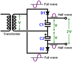
It is possible to increase the output voltage of a transformer although this does reduce its ability to supply current at that voltage. The way that this is done is to feed the positive cycles into one storage capacitor and the negative cycles into a second reservoir capacitor. This may sound a little complicated, but in reality, it isn't. A circuit for doing this is shown next to this paragraph.
With this circuit, the transformer output is some voltage, say "V" volts of AC current. This output waveform is fed to capacitor "C1" through diode "D1" which lops off the negative part of the cycle. This produces a series of positive half-cycles which charge up capacitor "C1" with a positive voltage of "V". The other half of the output is fed to capacitor "C2" through diode "D2" which cuts off the positive part of the cycle, causing capacitor "C2" to develop a voltage of -V across it. As the two capacitors are 'in series' and not placed across each other, their voltages add up and produce twice the transformer output voltage. A word of warning here. The transformer is producing an AC waveform and these are marked with the average voltage of the waveform, which is usually a sine wave. The peak voltage of a sinewave is 41% greater than this, so if your transformer has an AC output of 10 volts, then the peaks fed to the capacitors will be about 14.1 volts. If there is no current draw from the capacitors (that is, with the load switched off), then each capacitor will charge to this 14.1 volts and the overall output voltage will be 28.2 volts and not the 20 volts which you might expect. You need to understand that as this is only a half-wave supply, there will be considerable ripple on the output voltage if the current draw is high. Using one additional smoothing capacitor and paying attention to the voltage ratings of the capacitors, the 28 volts supply circuit might be like below: 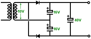
|
